Featured Post

High CMRR Instrumentation Amplifier (Schematic and Layout) design for biomedical applications

Instrumentation amplifiers are intended to be used whenever acquisition of a useful signal is difficult. IA’s must have extremely high input impedances because source impedances may be high and/or unbalanced. bias and offset currents are low and relatively stable so that the source impedance need not be constant. Balanced differential inputs are provided so that the signal source may be referenced to any reasonable level independent of the IA output load reference. Common mode rejection, a measure of input balance, is very high so that noise pickup and ground drops, characteristic of remote sensor applications, are minimized.Care is taken to provide high, well characterized stability of critical parameters under varying conditions, such as changing temperatures and supply voltages. Finally, all components that are critical to the performance of the IA are internal to the device. The precision of an IA is provided at the expense of flexibility. By committing to the one specific task of ...

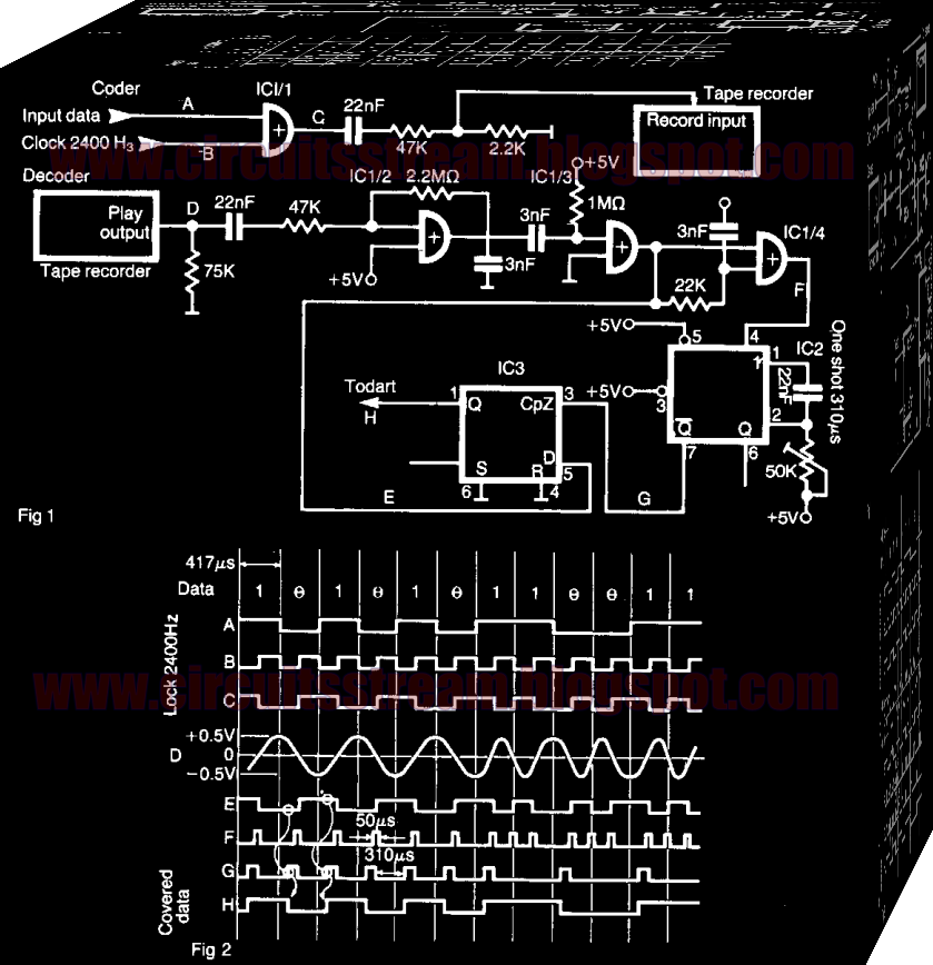
Simple Tape Recorder Interface Circuit Diagram

This is a Simple Tape Recorder Interface Circuit Diagram. However, you can record cassette tapes into any of these machines with an audio interface. The interface allows data to be saved on an ordinary tape recorder at a speed of 2400 bit/s. The serial stream of data Fig. 1 (A) is coded with a clock of 2400 Hz (B), by means of XOR gate IC 1/1. Logical `high` and `low` appear as shown in Fig. 2 (C). 

 Simple Tape Recorder Interface Circuit Diagram


These impulses are lowered in amplitude and feed into the record input of a low cost tape recorder. During the playback, pulses (D) are amplified with CMOS gate IC 1/2 connected as a linear amplifier, and providing a TTL level signal shown in (E). On both positive and negative transitions IC 1/4 forms short pulses as shown in (F) (approx. 50 *ts) that triggers one shot IC2. A monostable one shot pulse width is adjusted to be 3A of bit length (310 µß). 

A change from `high` to `low` in a coded stream generates a `low` pulse width of one bit cell. The same is for change from ' low'' to ' 'high'' that generates a `high` pulse of the same width. During this pulse one shot latches the state of line in D type flip-flop IC3 (G). When a stream consists of multiple `ones` or `zeros,` the one shot is retriggered before it comes to the end of the quasistable state and the state of the flip-flop remains unchanged. The original data stream is available at the output of the flip-flop (). Z80 the DUART that receives these pulses is programmed so that the receiver clock is 16 times the data rate (38.4 kHz).

Comments