Featured Post

High CMRR Instrumentation Amplifier (Schematic and Layout) design for biomedical applications

Instrumentation amplifiers are intended to be used whenever acquisition of a useful signal is difficult. IA’s must have extremely high input impedances because source impedances may be high and/or unbalanced. bias and offset currents are low and relatively stable so that the source impedance need not be constant. Balanced differential inputs are provided so that the signal source may be referenced to any reasonable level independent of the IA output load reference. Common mode rejection, a measure of input balance, is very high so that noise pickup and ground drops, characteristic of remote sensor applications, are minimized.Care is taken to provide high, well characterized stability of critical parameters under varying conditions, such as changing temperatures and supply voltages. Finally, all components that are critical to the performance of the IA are internal to the device. The precision of an IA is provided at the expense of flexibility. By committing to the one specific task of ...

Simple Electromagnetic Ring Launcher Circuit Diagram

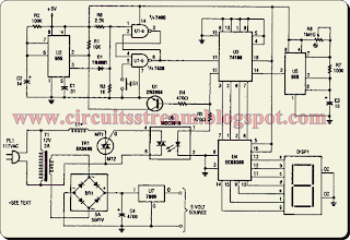
This is a Simple Electromagnetic Ring Launcher Circuit Diagram. The electromagnetic ring launcher is comprised of.four sub circuits: a clock circuit (built around U5, a 555 oscillator/timer configured for astable operation), a count-down/display circuit (built around U3), a 74190 synchronous up/down counter with BCD outputs that is configured for countdown operation; 

 Simple Electromagnetic Ring Launcher Circuit Diagram


Simple Electromagnetic Ring Launcher Circuit Diagram

U4, a ECG8368 BCD-to-7-segment latch/decoder/display driver; and DISP1, a common-cathode seven-segment display), a trigger circuit (comprised of U6), an MOC3010 opto isolator/ coupler with Triac-driver output; TR1, an SK3665 200-PIV, 4-A Triac; and a few support components), and a reset circuit (comprised of Ul, a 7400 quad 2-input NAND gate U2, a second 555 oscillator/timer configured for monostable operation; and a few support components). This circuit is that of a repulsion coil (LI) used to demonstrate the principle of electromagnetic repulsion by propelling a metal ring around the core of LI through the air. A countdown circuit is provided to count seconds before launch.

Comments