Featured Post

High CMRR Instrumentation Amplifier (Schematic and Layout) design for biomedical applications

Instrumentation amplifiers are intended to be used whenever acquisition of a useful signal is difficult. IA’s must have extremely high input impedances because source impedances may be high and/or unbalanced. bias and offset currents are low and relatively stable so that the source impedance need not be constant. Balanced differential inputs are provided so that the signal source may be referenced to any reasonable level independent of the IA output load reference. Common mode rejection, a measure of input balance, is very high so that noise pickup and ground drops, characteristic of remote sensor applications, are minimized.Care is taken to provide high, well characterized stability of critical parameters under varying conditions, such as changing temperatures and supply voltages. Finally, all components that are critical to the performance of the IA are internal to the device. The precision of an IA is provided at the expense of flexibility. By committing to the one specific task of

Model Rocket Launcher Circuit Diagram

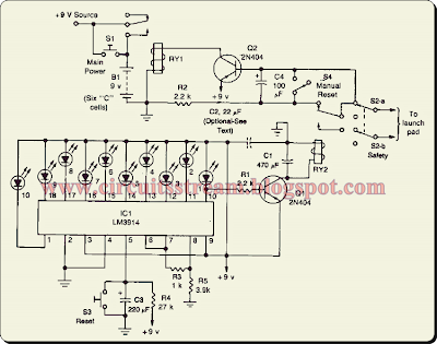
Model Rocket Launcher Circuit Diagram is a fun and educational hobby. However, it is important to always follow the safety rules for the most enjoyable experience. The circuit consists of the launch timer itself and an automatic-off timer. When power is applied to that IC, the countdown LED's sequence is on until they are all lit. When the last one LED1, is fully lit, transistor Ql saturates, energizing RY2. 

 Model Rocket Launcher Circuit Diagram


 Model Rocket Launcher Circuit Diagram

When that happens, a circuit between the lantern battery at the launch pad and the nickel-chromium wire is completed; the wire heats up as before, and the rocket is launched. Resistor R4 and capacitor C3 determine the countdown timing; with the values shown it should be approximately 10 seconds. Resistors R3 and R5 set the LED brightness. Safety is of the utmost importance. 

That's the purpose of the second half of the circuit. When RY2 opens, the current flow to Q2 is disrupted. But, because of the presence of R2 and C4, the transistor remains saturated for about 3 seconds. After that, however, the transistor stops conducting and RY1 is de-energized. That cuts off the power to the rest of the circuit, and RY2 de-energizes again, breaking the circuit to the launch pad. Switch S3 is used to reset the countdown. Once that is done, pressing Si starts the launch sequence; the rest is automatic. Switch S4 is used to latch RY1 manually if needed.

Comments