Featured Post

High CMRR Instrumentation Amplifier (Schematic and Layout) design for biomedical applications

Instrumentation amplifiers are intended to be used whenever acquisition of a useful signal is difficult. IA’s must have extremely high input impedances because source impedances may be high and/or unbalanced. bias and offset currents are low and relatively stable so that the source impedance need not be constant. Balanced differential inputs are provided so that the signal source may be referenced to any reasonable level independent of the IA output load reference. Common mode rejection, a measure of input balance, is very high so that noise pickup and ground drops, characteristic of remote sensor applications, are minimized.Care is taken to provide high, well characterized stability of critical parameters under varying conditions, such as changing temperatures and supply voltages. Finally, all components that are critical to the performance of the IA are internal to the device. The precision of an IA is provided at the expense of flexibility. By committing to the one specific task of ...

Digital Electronic Slot Machine Circuit Diagram

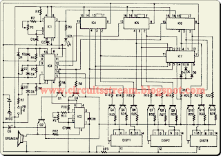
Most modern slot machines are designed to look and feel like the old mechanical models, but they work on a completely different principle. The outcome of each pull is actually controlled by a central computer inside the machine, not by the motion of the reels.. The slot machine`s realistic action is provided by seven ICs and three displays, as shown.Read : Tica Tak Electronic Dice Circuit Diagram

 Digital Electronic Slot Machine Circuit Diagram


Digital Electronic Slot Machine Circuit Diagram


Two 555 CMOS timer ICs generate pulses. IC1 is used to generate the clock pulses for the entire electronic slot machine. The pulses are coupled from the output (pin 3) to the clock inputs of IC4, IC5, and 1C6, the display-driver ICs. The displays are common-cathode 7-segment LED types. They are wired to display three different symbols, an L, a 7, and bar, When all three displays show the same symbols, IC7 (a 4023 triple 3-iriput NAND gate) decodes a winner and sends a signal to pin 5 of IC3. Read: Build a Toy Siren Circuit Diagram

That IC is a 4001 CMOS NOR gate and it turns on IC2, a 555 timer IC. IC2 actually produces the winner tone on its output, pin 3. Transistors Q4 through Q12 are used to drive the common-cathode displays. An LED is used to indicate the clock pulses, and a variable resistor is provided for each of these functions. Trimmer resistor PI controls the overall clock rate, P2 controls the winner tone, and P3 controls the display brilliance.


Comments