Featured Post

High CMRR Instrumentation Amplifier (Schematic and Layout) design for biomedical applications

Instrumentation amplifiers are intended to be used whenever acquisition of a useful signal is difficult. IA’s must have extremely high input impedances because source impedances may be high and/or unbalanced. bias and offset currents are low and relatively stable so that the source impedance need not be constant. Balanced differential inputs are provided so that the signal source may be referenced to any reasonable level independent of the IA output load reference. Common mode rejection, a measure of input balance, is very high so that noise pickup and ground drops, characteristic of remote sensor applications, are minimized.Care is taken to provide high, well characterized stability of critical parameters under varying conditions, such as changing temperatures and supply voltages. Finally, all components that are critical to the performance of the IA are internal to the device. The precision of an IA is provided at the expense of flexibility. By committing to the one specific task of ...

Artificial random Simulated Flicker Sequencer Circuit Diagram

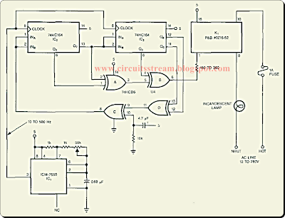
Artificial random Simulated Flicker Sequencer Circuit Diagram, The artificial random sequencer drives a solid-state relay. If you power a low-wattage lamp from the relay, the lamp will appear to flicker like a candle`s flame in the wind; using higher-wattage lamps allows you to simulate the blaze of a fireplace or campfire. 

 Artificial random Simulated Flicker Sequencer Circuit Diagram


 Artificial random Simulated Flicker Sequencer Circuit Diagram


You can enhance the effect by using three or more such circuits to power an array of lamps. The circuit comprises an oscillator, IC1, and a 15-stage, artificial random sequencer, IC2-4. The sequencer produces a serial bit stream that repeats only every 32 767 bits. 

Feedback from the sequencer`s stages 14 and 15 go through IC4D and back to the serial input of IC2. Notice the RC network that feeds IC4C; the network feeds a positive pulse into the sequencer to ensure that it won`t get stuck with all zeros at power-up. The leftover XOR gates IC4A and IC4B further scramble the pattern. The serial stream from IC4B drives a solid-state relay that features zero-voltage switching and can handle loads as high as 1 A at 12 to 280 Vac.

Comments