Featured Post

High CMRR Instrumentation Amplifier (Schematic and Layout) design for biomedical applications

Instrumentation amplifiers are intended to be used whenever acquisition of a useful signal is difficult. IA’s must have extremely high input impedances because source impedances may be high and/or unbalanced. bias and offset currents are low and relatively stable so that the source impedance need not be constant. Balanced differential inputs are provided so that the signal source may be referenced to any reasonable level independent of the IA output load reference. Common mode rejection, a measure of input balance, is very high so that noise pickup and ground drops, characteristic of remote sensor applications, are minimized.Care is taken to provide high, well characterized stability of critical parameters under varying conditions, such as changing temperatures and supply voltages. Finally, all components that are critical to the performance of the IA are internal to the device. The precision of an IA is provided at the expense of flexibility. By committing to the one specific task of

Low Pass Filter Circuit Diagram

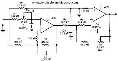
Simple and Fast Response Settling Low-Pass Filter. By introducing an extra transmission zero to the stopband of a low-pass filter, a sharp roll-off characteristic can be obtained. The filter design example of Fig. 30-l(a) shows that the time-domain performance of the low-pass section can also be improved. Figure 30-1 (b) shows the attenuation characteristic of the proposed circuit. Position of the transmission zero is determined by the passive components around the first op amp. 

It was chosen to obtain 60 dB of rejection at 60 Hz. A suitable fourth-order Bessel filter has the frequency response, as shown by the dashed line. Its response to a step input is characterized by settling time to 0.1 % of 1.8 -f Fc = 180 ms. Figure 30-l(c) and 30-l(d) represent the step response for the filter of Fig. 30-l(a) in both normal and expanded voltage scales. As you can see, settling time to 0.1% is below 100 ms; overshoot and ringing, stay below 0.03%. 


Low Pass Filter Circuit Diagram


This quite significant speed and accuracy improvement can be a major factor, particularly for low-frequency applications. Averaging filter for low-frequency linear or true rms ac-to-dc converters is an example. Some anti-aliasing applications can also be considered. For best results, resistance ratios R4-rR5 = 20, Re + R$=1A, and capacitance ratios C3 + C2 = C3 -f C4 = 4.7 should be kept up for any selected Fc.

Comments