Featured Post

High CMRR Instrumentation Amplifier (Schematic and Layout) design for biomedical applications

Instrumentation amplifiers are intended to be used whenever acquisition of a useful signal is difficult. IA’s must have extremely high input impedances because source impedances may be high and/or unbalanced. bias and offset currents are low and relatively stable so that the source impedance need not be constant. Balanced differential inputs are provided so that the signal source may be referenced to any reasonable level independent of the IA output load reference. Common mode rejection, a measure of input balance, is very high so that noise pickup and ground drops, characteristic of remote sensor applications, are minimized.Care is taken to provide high, well characterized stability of critical parameters under varying conditions, such as changing temperatures and supply voltages. Finally, all components that are critical to the performance of the IA are internal to the device. The precision of an IA is provided at the expense of flexibility. By committing to the one specific task of

Best Electronic Crowbar Circuit Diagram for AC or DC lines

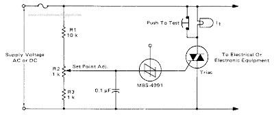
This is Best Electronic Crowbar Circuit Diagram for AC or DC lines. For positive protection of electrical or electronic equipment, use this against excessive supply voltage. Due to improper switching, wiring, short circuits, or failure of regulators, an electronic crowbar circuit can quickly place a short circuit across the power lines, thereby dropping the voltage across the protected device to near zero and blowing a fuse. 

The triac and SBS are both bilateral devices, the circuit is equally useful on ac or dc supply lines. With the values shown for Rl, R2, and R3, the crowbar operating point can be adjusted over the range of 60 to 120 volts dc or 42 to 84 volts ac. The resistor values can be changed to cover a different range of supply voltages. The voltage rating of the triac must be greater than the highest operating point as set by R2, II is a low power incandescent lamp with a voltage rating equal to the supply voltage. 


Best Electronic Crowbar Circuit Diagram for AC or DC lines

It may be used to check the set point and operation of the unit by opening the test switch and adjusting the input or set point to fire the SBS. An alarm unit such as the Mallory Sonalert may be connected across the fuse to provide an audible indication of crowbar action. (This circuit may not act on short, infrequent power line transients).

Comments