We have developed an instrument for
performing a visual field test built into a pair of glasses. A visual
field test maps out a patient’s visual field including peripheral vision
and blind spots, and is useful for the diagnosis of several ocular and
neural degenerative diseases including glaucoma, stroke, and brain
tumors. Existing devices are bulky and expensive. We were able to create
a low cost, portable version of this tool which makes it more
accessible to doctors.

High Level Design
Rationale and Source of Project Idea
We
discovered a link to a lab used in a bioinstrumentation class regarding visual perception experiments. Their
project involved designing an astable miltivibrator circuit to blink an
LED at a variable rate. This device was then used to measure the visual
fusion rate, the fastest frequency of blinking that could be observed
before the light appeared to be continuously on, and to observe
differences between the perceived blink rate at the center and periphery
of the visual field. Upon further research into visual perception
experiments, we discovered another lab from a course at Stanford
University which described techniques for measuring peripheral vision
and locating blind spots by having a partner move their finger or the
tip of a pencil along a plane parallel and approximately 1-2 feet from
the observer’s face until the observer can no longer see the object.
With these ideas in mind, we set out to make an automated device which
could measure the difference in peripheral vision for different blink
rates and map the location of blind spots within the field of view.
Our device is an example of an automated perimeter,
an automated device which can measure field of view. Measuring the
visual field is an important tool for detecting glaucoma and other
ocularly degenerative disorders because they are often caused by damage
to nerve fibers in a particular location and distribution in the eye.
There are several different techniques currently used to measure
peripheral vision. The simplest is the confrontation technique, during
which the optometrist simply sits across from the patient, asks them to
cover one eye, and then holds up a variable number of fingers in the
patients periphery. While this technique is extremely inexpensive
(free!) to implement, it is not very precise and may only indicate that
further tests are required to diagnose any possible issues. The tangent
screen is a more sophisticated perimeter which can measure the angles to
the edge of the visual field more accurately, however these devices are
usually large, expensive, and uncomfortable for the patient. The
patient rests their face against a chin rest while the technician moves
an object around a hemispherical dome to measure the field of view. The
most common iteration of this design is the Goldmann-type projection
perimeter (shown below), an automated device which projects a spot to
various locations on a hemispherical screen.

Goldmann-type Projection Perimeter (photo courtesy of Carleton Optical)
We propose that by incorporating the device into a
pair of glasses we can achieve the same accuracy of visual field
measurements while making the experience easier for the patient and the
equipment less expensive for the doctors.
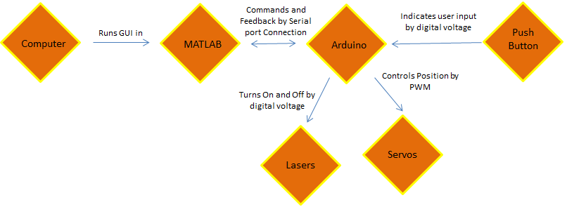
Logical Structure
High-level block diagram.
Hardware and Software Tradeoffs
Other than the required hardware like the servos and
lasers, everything was implemented using software. Although we
originally considered implementing some features, the variable blink
rate for example, using analog circuitry, we ultimately determined that
it would be much more straightforward to implement our design using a
microcontroller. Since our design required precise servo control anyway,
using the microcontroller was definitely the simpler choice (which was
important to consider due to our limited time limit). The Arduino model
we used can be purchased for less than $10, so this did not
significantly impact the cost of developing our design.
Existing Patents
Perimeter designs were first registered by the patent office in the
late 1800’s when the tangent screen method was developed and used by
Bjerrum and Ronne to demonstrate characteristics of visual field loss in
glaucoma. Early designs measured along an arc which passed horizontally
in front of the patients eyes. The arc later became a bowl shape, which
allowed doctors to observe the off-axis field of view. The Goldmann
Bowl, still the most common design used today, was patented in 1945.
Since then, many patents have been issued for slight modifications to
this design. While we were able to find some patents for portable
perimeters (including one which folded into a suitcase) any that were
automated were still large and meant to be used on a tabletop. We did
not find any patents for an automated perimeter as portable as our
glasses-mounted design.
Hardware Design

Our hardware design is relatively simple because we
chose to use an Arduino Pro Mini single-board microcontroller instead
of a complicated analog circuit. The arduino is powered and connected to
the computer through a USB FT232R breakout board from sparkfun.com.
Four Dagu Micro servos are connected to digital PWM pins on the Arduino
and are powered using a lab bench 5V DC power supply. Two 100 μF
capacitors are connected between 5V and ground to reduce noise from the
servos. Two of the servos rotate clockwise from 0 to 180 degrees, and
the other two rotate counterclockwise from 0 to 180 degrees. One servo
is attached with hot glue to each arm of a pair of sunglasses without
lenses with the flywheel parallel to the floor. A second servo is
mounted with hot glue on each of the horizontal flywheels with the new
servos rotating in a plane perpendicular to the floor. The servos are
arranged so that increasing the angle rotates the flywheel from the
center to the edge of the field of view along the x axis and upwards for
the y axis. Two .5 mW COM-00594 red laser card modules, also from
sparkfun.com, are connected via TIP31 transistors to digital voltage
pins on the Arduino through 1 Kohm resistors to limit the current and
are powered using to DC power supply with a 3 V regulator. The lasers
are hot glued to each of the servos which rotate in the vertical plane.
The result is a pair of lasers mounted on glasses frames with two
degrees of freedom along which they can scan. The wires from the Arduino
to the galsses are bundled together through pieces of telephone wire
with connector pins soldered to the ends to facilitate setup and
operation of the device.

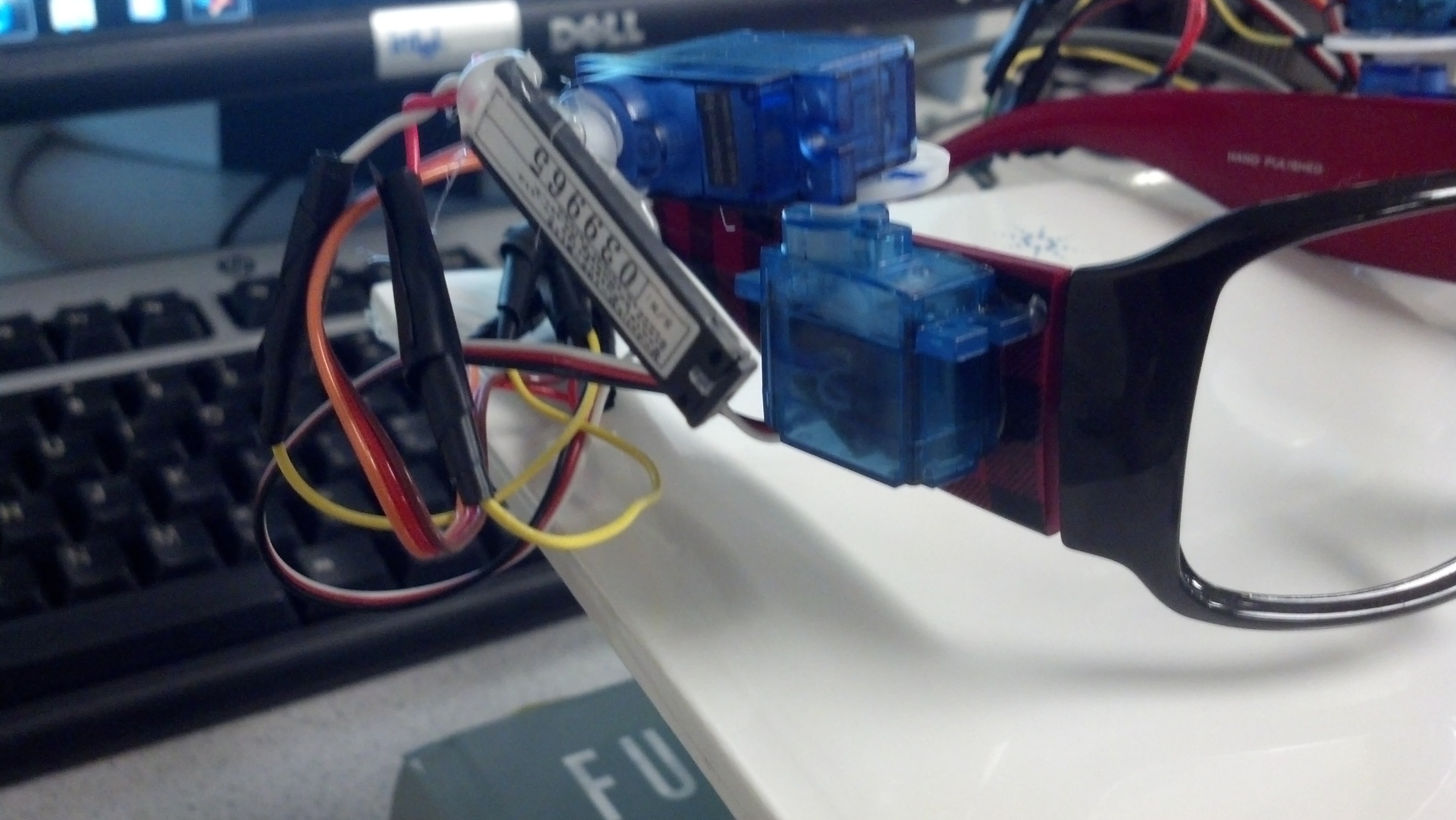
Close up of one arm.
Issues
We would like to note that we had a lot of issues obtaining a
functional set of motors. In our original order we received 3 servos
which rotated counterclockwise and one which rotated clockwise. Upon
inquiry of why the four were not identical, we were sent a replacement
which turned out to be defective (it drew a destructively high current
of approximately .5 A). Ultimately we ordered 4 additional servos and
asked for another replacement. In the end we were able to obtain 4
motors which functioned reasonably well and rotated the proper
direction, however they seem to be worsening with use. The motors tend
to click when positioned at the extremes, the motion is sometimes
choppy, and one motor will walk the flywheel in a circle if ever set to
zero. We definitely struggled with these motors and would consider a
different model for future prototypes if one could be found with similar
specifications.
Software Design
Our program consists of two parts, one run in Matlab
(perimeterGui.m) and one run on the Arduino (aglasses.ino), which
communicate via serial connection. The Matlab portion contains the
master controls, while the Arduino controls the servos based upon
commands it receives from Matlab.
The Files
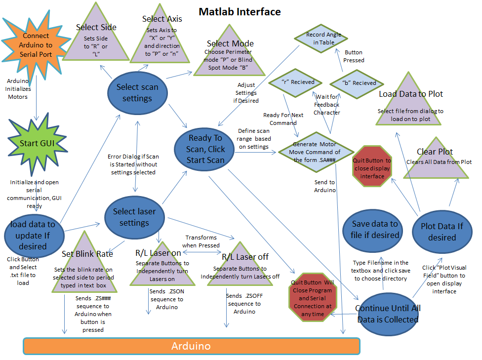
perimeterGui.m
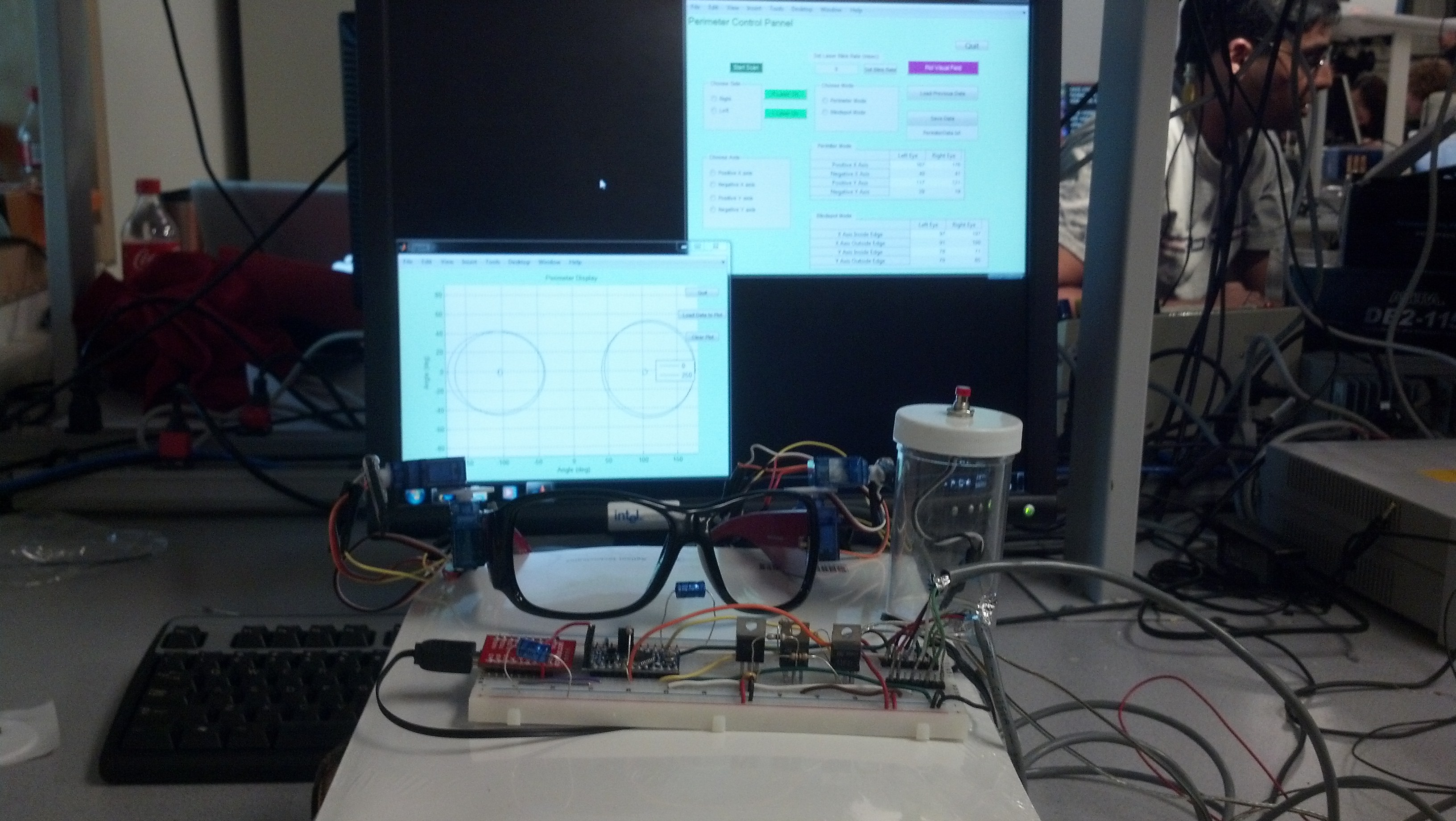
When the “perimeterGui.m” script is started, Matlab
first establishes a serial connection with the Arduino, then opens the
GUI window on the screen. Several controls are initialized on the GUI
including buttons to turn the lasers on an off, “Quit” and “Start Scan”
buttons, and three groups of radio buttons to choose the eye and axis to
be scanned and to choose between perimeter mode (for peripheral vision)
or blind spot mode. The operator can then control the Glasses Mounted
Automated Perimeter entirely from this GUI window, which was designed so
that the command line would be active while the program was running in
case any commands need to be send manually. Two tables in the GUI window
display the data as it is being collected, and the results can be
plotted using the “Plot Visual Field” button.
Control Panel GUI
When the operator is performing the visual field
test, they would collect data for each of the possible scans by choosing
each possible combination of the radio buttons. We chose this design
because it allows the operator to perform the scans in any order and
repeat them as many times as necessary without having to restart the
test from the beginning. Since the arduino reads one ASCII character
from the serial buffer at a time, radio button selections specify the
character values of certain Matlab variables to be sent to the Arduino.
The first radio button group “Choose Side” sets a variable “side” to “R”
for right eye and “L” for left to specify the eye being scanned. The
second set of radio buttons is “Choose Axis” which allows the operator
to choose between X or Y axis scans and the direction to scan from the
center of the field of view (“P” for positive and “N” for negative”).
The third group of radio buttons allows the user to choose between
perimetry mode (“P”) and blind spot mode (“B”). When the operator
presses the “Start Scan” button, the program first checks to make sure a
selection is made in each radio group. If not, the program generates
and error dialog box instructing the operator on how to correct their
settings. MATLAB then sends a series of commands to the Arduino to move
the specified motor in 1 degree steps every quarter second along the
axis and direction indicated by the radio buttons. These commands will
always have the form “.SA###” where the “.” indicates to the Arduino
that this is a command it should execute, “S” is the side and will be
either “R” or “L”, “A” is the axis and will be either “X” or “Y” and
“###” is the angle the selected servo should move to. Upon sending each
command, Matlab then waits to receive a character “r” from the Arduino
indicating that it is ready to receive the next angle. This handshaking
ensures that angles are not skipped because of buildup of the buffer or
timing issues of communication through the serial port. This was the
trickiest part to write because we had to adjust the timing of the
communication until there were no glitches. In the end, there still
seems to be a backup of commands in the serial buffer, however it does
not affect the functionality of the device. When the patient presses the
button indicating that they can no longer see the spot, the arduino
sends a “b” instead of an “r,” indicating that the button was pressed,
followed by the angle the servo was at. When Matlab receives the “b,” it
stops sending angles to the arduino and records the angle received from
the Arduino in the appropriate cell in the tables in the GUI window.
In addition to controlling the type of scan to be
performed, each laser can be turned on and off independently with the
green “R Laser On” and “L Laser On” buttons in the GUI window. For
safety reasons, the color and label on these buttons toggles each time
they are pressed. If the lasers are on, the buttons are red and are
labeled “R Laser Off” and “L Laser Off.” When pressed, these buttons
trigger Matlab to send a command of the form “.ZSON” or “.ZSOFF”
respectively, where the “.” indicates to the Arduino that this is a
command it should execute, "Z" indicates a laser command, “S” is a
character representing the side (either “L” or “R”), the “L” indicates
that this is a command for the lasers, and “ON” and “OFF” tell the
Arduino which action to take. The lasers can also be set to have a
variable blink rate so that the field of view can be measured with
different blink rates of the laser. The blink rate is changed by
ensuring that the correct side is chosen in the “Select Side” group of
radio buttons, typing the desired period of the blink rate into the box
labeled “Set Laser Blink Rate” and then clicking the adjacent button.
This sends a command to the Arudino of the form ".ZS###" where ### is
the blink period in ms.The selected period will only be valid for one
laser at a time. Because of the way blinking was implemented, the
Arduino cannot accurately control the blink rate of both lasers
simultaneously.
The GUI window is initialized for the operator to
collect completely new data, however they have the option to update
previously recorded data. Previously collected data can be loaded using
the “Load Previous Data” button, which brings up a dialog box allowing
the operator to choose the .txt file containing the data they wish to
update. There is also a “Save Data” button, which saves the data
currently displayed in the tables to the .txt file named in the box
below the button.
In order to display the data visually, we have
included the “Plot Visual Field” button, which plots the data currently
listed in the tables. When this button is pressed, a new window
containing a plot is opened. In order to display the data, we
approximate the visual field and blind spot of each eye as an ellipse
defined by four points at the ends of the major and minor axes. An
ellipse is drawn representing the borders of the visual field and the
blindspot of each eye using the downloaded Matlab function “ellipse.m,”
which is created and copyrighted by David Long, but is available for use
as long as the license is retained with the code (see code appendix).
Also in this window is a “Load Data” button which allows the operator
to load multiple data sets simultaneously and observe them, and a “Clear
Plot” button which erases all data currently on the plot. This script
can also be run independently of the control GUI to observe perviously
collected data while the perimeter is not connected to the serial port.

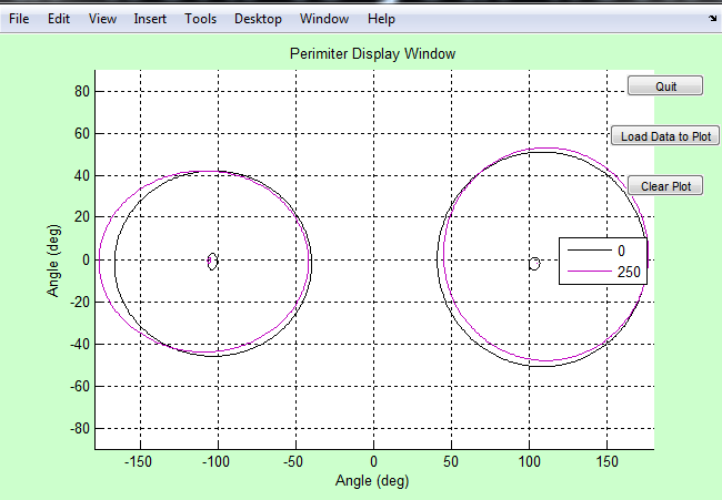
Data Plot GUI
Both the GUI window and plot window also contain a “Quit”
button. When the button is pressed from the plot window only the plot
window is closed. When the one in the GUI window is pressed, Matlab
closes the serial connection to the Arduino and closes both windows.
Matlab code structure
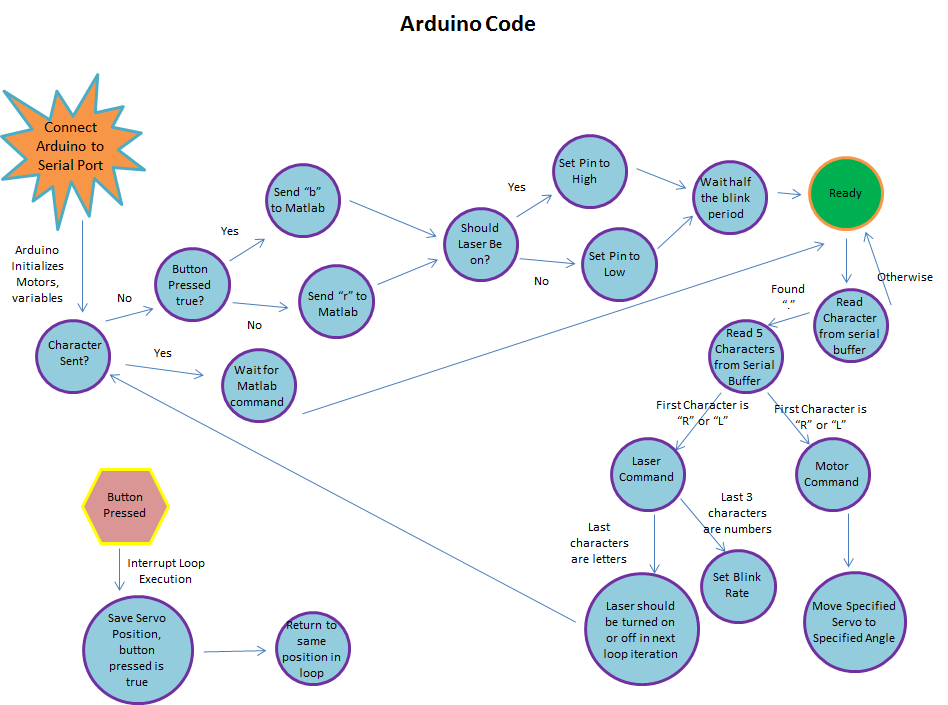
aglasses.ino
The Arduino code aglasses.ino serves as a hardware
driver. The code loops endlessly while it waits for a command to be
sent from Matlab over the serial connection of the format “.-----”. The
‘.’ is used so that any noise or junk data will not be followed as
serious command. Available commands to the aglasses.ino include servo
commands, laser activation commands, and laser blink commands.
“.RX###” is a servo command that will cause the
right x-axis servo to move to angle ###. All servo angle commands
follow this format where L can replace R and Y can replace X to control
the left side and y-axis respectively. A delay is hard coded so that
the servo has enough time to reach its destination angle before further
commands will be heard.
“.ZRON-” and “.ZROFF” will turn the right laser on
and off respectively; here R can be replaced with L to control the left
laser. Actual laser states are altered in the main loop while waiting
for a Matlab command.
“.ZR###” will cause the right laser to blink with a
period of ### milliseconds; here R can be replaced with L to control
the left laser. The current implementation of laser blinking is
imprecise and works by waiting half of the period, then toggling the
laser in the main loop while waiting for the next command from Matlab.
Upon receiving a command and executing the
appropriate action, the aglasses.ino code will send Matlab a “rz” string
followed by a “###z” string where ### is the latest servo angle set.
The “rz” string will notify Matlab that the Arduino is ready for
further commands and the “###z” string lets Matlab know the status of
the servos in the real world. The ‘z’ at the end of the strings is the
agreed Matlab terminator.
If the push button is ever pressed, aglasses.ino
immediate halts whatever it is doing and falls into an interrupt service
routine. In the interrupt, a flag is set to send Matlab a different
string and the latest angle any servo was set to is stored in a secure
buffer. The interrupt then ends and aglasses.ino resumes doing whatever
it was doing before the interrupt occurred. The next string sent to
Matlab is then “bz” followed by “###z” where the “bz” notifies Matlab of
the button press and the “###z” string contains the saved angle.
Arduino code structure
Programming Issues
The most difficult part of this project was controlling the timing of
communication between Matlab and the Arduino. In our final program,
there seems the be a delay of approximately 4 degrees between the angle
MATLAB sends, and the angle the Arduino sends to the motors. The Matlab
code seems to send 4 angles before the servos begin to move. After much
exasperation, we are unable to determine the cause of this delay; in
fact, it seems to disappear when we step through the code slowly.
Fortunately, this does not affect the functionality of the perimeter.
The angle recorded by the program is actually the position of the servo
when the button was pressed and not the most recent angle sent by
Matlab, so the delay has no effect on the results. Previously we also
experienced an issue from sending Matlab commands to quickly. We
overflowed the input buffer to the Arduino, which caused the servo to
move to weird angles in the middle of a scan. We have since fixed this
issue by clearing the serial buffers more frequently.
Testing
Because the project was completed in stages, it was
also tested in stages. When we were wiring the Arduino on the
breadboard to accept programming through the usb interface, we attempted
a simple blinking of the built in LED. Once the LED was blinking as
the programming should have dictated, we knew the device was wired to
the usb interface correctly.
The hardware is all directly controlled by the
Arduino and so extensive testing was done after the rest of the hardware
was wired. We found that not all of the servos behaved the same; some
spun the opposite 180 degrees, but through the use of print statements
and observing physical motion of servos we found all the proper control
schemes.
After the hardware was settled, we needed to test
Matlab’s ability to indirectly control things. The serial connection
between the Arduino and Matlab was tested by sending a serial message to
the Arduino and then sending that same message back to Matlab. We were
unable to view the message until it returned to Matlab, because using
the serial interface eliminated the Arduino’s ability to print to the
control pane. Once the messages received by Matlab were the same ones
it sent, individual commands were sent and were found to work as
intended.
Once initial commands were functional, we began to
send more complex commands in running a scan. By observing the physical
servos on the glasses, we noticed that the angles displayed in the code
were not the same as the angles the servo were physically at. This was
confirmed and corrected for by sending additional information from the
Arduino back to Matlab. Since the Arduino was actually setting the
angle of the servo, its knowledge of the angle was taken to be true.
Future work that depended on precise angles thereafter used the
additional angle information sent by the Arduino.
Blind spot measurements were tested by the patient
manually finding their blind spot and comparing that spot to the laser’s
position.
Results
Speed of Execution
Our design allows for one degree of servo motion every quarter
second without any significant hesitation or periods of non-intentional
inactivity. Based on our literature search, 4 degrees per second is
considered the optimal rate for automated perimetry. Approximately 5-10
minutes are required to collect data for one patient, which is
comparable to the approimately 7 minutes per eye for the Goldmann
perimeter. Additionally our patient interface, the push button, is
extremely responsive and stops the servos immediately, exactly as it
should.
Accuracy
Our results are reliably precise; patients receive the same personal
data after repeated testing. While the accuracy of the full range of
view results could be tested via protractors, it was not verified. The
blind spots however, were easily tested by simple means and verified.
For one patient, the field of view was consistently significantly
smaller for the left eye than the right eye. We suspect this is caused
by a known difference in nearsightedness or possibly a known astigmatism
in the left eye, however this has not been verified.
Collected data
In the above trials, the first data set is Patient 1, the next are
Patient 2, and the final two are Patient 3. Among the same patient, the
data between trials is well correlated. This shows that our device is
precise in its operation. Note the blink periods next to the line colors
in the legend; data sets of the same patient seem correlated even with
varying blink periods.
Safety
As always, safety was a primary concern throughout this project.
From the beginning we identified the lasers as the most likely source
of danger. To counter this we chose very low power lasers to minimize
damage even in cases of direct eye contact. To further ensure the
safety of ourselves and our labmates, we tested in a corner so that no
lasers would be shot around the lab. The gui display of the laser
controls shows the lasers as green when off and red when on, so as to
remind the technician of possible dangers. As a final precaution, the
default state of the system is set to have the lasers off and a very
precise command must be given to turn them on. This setup ensures that
even in a situation in which the Arduino is randomly reset or plagued
with random noise as signal, the lasers will remain off and safe.
Telephone wire was used to bundle wires in order to reduce patient
entanglement in the wires connecting the Arduino to the Glasses Mounted
Automated Perimeter. Any and all exposed wires or connections were
wrapped in electrical tape to ensure patient and operator safety.
Interference with other's Designs
Because of the nature of our project, there should not be any
interference with other people’s designs. The servos make minimal noise
and the only light generated is an extremely directed laser beam.
Unless the other projects were using very sensitive audio equipment or
were directly in the path of the lasers (between us and the corner), no
interference seems possible.
Useability
The Glasses Mounted Automated Perimeter can be used by any
patient with limited instruction. The glasses themselves are
one-size-fits-all and the person’s height has no bearing on the device’s
function. The patient interface is a simple pushbutton and requires
little dexterity or strength to use properly.
The technician side of the device is slightly more
complex than the patient side, but still requires no extensive training.
The technician does not need any medical training nor do they require
an in-depth knowledge of the theory or how the system works. Because of
the minimal requirements placed on the patient and operator, the Glasses
Mounted Automated Perimeter can be used by nearly anyone.
Conclusions
Meeting of Expectations
In general, we were very pleased with the functionality of
our design. We were able to accomplish everything we set out to do in
the project proposal. Our device maps out field of view and blind spots
with high precision in repeated trials, and we are able to control the
perimeter reliably from the GUI. We are also able to collect field of
view data at varying blink rates, although we did not notice a
significant change for different rates.
Things we would do Differently
While our design functions very well, there are definitely
improvements to be made. Currently the glasses are connected to the
Arduino through very long wires and a bread board. These wires are
unruly and become easily tangled, making the glasses more difficult to
take on and off and increasing the risk of damage to the device. We
would like to develop a wireless version to avoid these issues and
further increase the portability. The perimeter draws approximately .08
mA while operating, so the motors can be powered by battery. The
positions of the lasers are calibrated for a patient standing one foot
away from the wall, however this distance is difficult to maintain. In
order to improve the placement of the stationary spot during scans, we
would like to implement distance sensors which alert the patient when
they are the appropriate distance from the wall or adjust the angles for
the new distance. One of the benefits of the glasses mounted design is
that the results are independent of sideways head head tilts, however
the results will be affected if the distance from the patient to the
wall changes. In order to compensate for these head movements, we would
like to add a gyroscope to the glasses so that the position of the beams
can be corrected for head movements. We would also like to include eye
tracking sensors to evaluate how well the patient is able to focus on
the stationary spot during the scan to improve evaluation of the quality
of collected data or to reposition the beams. One shortcoming of our
design is that it currently only looks for blind spots which occur along
the X axis we scan. While this is effective for detecting normal blind
spots, vision degeneration can also occur off-axis. In order to improve
glaucoma detection, we would like to implement a “Glaucoma Mode,” which
quickly performs a 2D raster scan to locate possible problem areas in
the visual field. Once regions of interest are determined, the
technician would be able to scan along any horizontal or vertical line
to map out the shape of the affected area. We chose not to implement
glaucoma mode at this time because we were having some difficulty
controlling the motors at the extremes of the range. We would like to
find new motors before adding this functionality. Lastly, our display
method makes the assumption that the field of view and blind spots can
be approximated as an ellipse by defining the limits of the major and
minor axes. While this is often true for healthy individuals, glaucoma
spots can be oddly shaped. Once the 2D scan method is implemented, we
will be able to define these regions using more points which are not
confined to one vertical and one horizontal axis. This would greatly
improve the accuracy of our results.
Appendices
A. Source Code
perimeterGui.m
Necesarry Files
aglasses.ino
B. Schematics
Full schematic of our circuitry
C. Instructions for Use
Patient:
- Put on glasses
- Technician will indicate where to stand 1 ft away from the wall in a corner
- Try to keep head as stationary as possible
- Focus on stationary spot while observing moving spot with peripheral vision
- Press button when you can no longer see the spot. The
technician will inform you whether to look for the edge of visual field
or the edge of your blindspot.
Technician:
- Start PerimeterGui.m
- Select scan settings
- Perform a scan for each permutation of settings by clicking “Start Scan”
- Save and load data using buttons in GUI
- Use “Plot Visual Field” button to observe results graphically and compare to previously collected data.