The 8051 microcontroller has two
independent 16 bit up counting timers named Timer 0 and Timer 1 and this
article is about generating time delays using the 8051 timers.
Generating delay using pure software loops have been already discussed
here but such delays are poor in accuracy and cannot be used in
sensitive applications. Delay using timer is the most accurate and
surely the best method.
A timer can be generalized as a
multi-bit counter which increments/decrements itself on receiving a
clock signal and produces an interrupt signal up on roll over. When the
counter is running on the processor’s clock , it is called a “Timer”,
which counts a predefined number of processor clock pulses and
generates a programmable delay. When the counter is running on an
external clock source (may be a periodic or aperiodic external signal)
it is called a “Counter” itself and it can be used for counting external
events.
In 8051, the oscillator output is
divided by 12 using a divide by 12 network and then fed to the Timer as
the clock signal. That means for an 8051 running at 12MHz, the timer
clock input will be 1MHz. That means the the timer advances once in
every 1uS and the maximum time delay possible using a single 8051 timer
is ( 2^16) x (1µS) = 65536µS. Delays longer than this can be implemented
by writing up a basic delay program using timer and then looping it for
a required number of time. We will see all these in detail in next
sections of this article.
Designing a delay program using 8051 timers.
While designing delay programs in 8051, calculating the initial value
that has to be loaded inot TH and TL registers forms a very important
thing. Let us see how it is done.
- Assume the processor is clocked by a 12MHz crystal.
- That means, the timer clock input will be 12MHz/12 = 1MHz
- That means, the time taken for the timer to make one increment = 1/1MHz = 1uS
- For a time delay of “X” uS the timer has to make “X” increments.
- 2^16 = 65536 is the maximim number of counts possible for a 16 bit timer.
- Let TH be the value value that has to be loaded to TH registed and TL be the value that has to be loaded to TL register.
- Then, THTL = Hexadecimal equivalent of (65536-X) where (65536-X) is considered in decimal.
Example.
Let the required delay be 1000uS (ie; 1mS).
That means X = 1000
65536 – X = 65536 – 1000 = 64536.
64536 is considered in decimal and converting it t0 hexadecimal gives FC18
That means THTL = FC18
Therefore TH=FC and TL=18
Program for generating 1mS delay using 8051 timer.
The program shown below can be used for
generating 1mS delay and it is written as a subroutine so that you can
call it anywhere in the program. Also you can put this in a loop for
creating longer time delays (multiples of 1mS). Here Timer 0 of 8051 is
used and it is operating in MODE1 (16 bit timer).
DELAY: MOV TMOD,#00000001B // Sets Timer 0 to MODE1 (16 bit timer). Timer 1 is not used
       MOV TH0,#0FCH // Loads TH0 register with FCH
       MOV TL0,#018H // LOads TL0 register with 18H
       SETB TR0 // Starts the Timer 0
HERE: JNB TF0,HERE // Loops here until TF0 is set (ie;until roll over)
      CLR TR0 // Stops Timer 0
      CLR TF0 // Clears TF0 flag
      RET
The above delay routine can be looped twice in order to get a 2mS delay and it is shown in the program below.
MAIN: MOV R6,#2D
LOOP: ACALL DELAY
      DJNZ R6,LOOP
      SJMP MAIN

DELAY: MOV TMOD,#00000001B
       MOV TH0,#0FCH
       MOV TL0,#018H
       SETB TR0
HERE: JNB TF0,HERE
      CLR TR0
      CLR TF0
      RET
Few points to remember while using timers.
- Once timer flag (TF) is set, the programmer must clear it before it can be set again.
- The timer does not stop after the timer flag is set. The programmer must clear the TR bit in order to stop the timer.
- Once the timer overflows, the programmer must reload the initial
start values to the TH and TL registers to begin counting up from.
- We can configure the desired timer to create an interrupt when the TF flag is set.
- If interrupt is not used, then we have to check the timer flag (TF) is set using some conditional branching instruction.
- Maximum delay possible using a single 8051 timer is 65536µS and
minimum is 1µS provided that you are using a 12MHz crystal for clocking
the microcontroller.
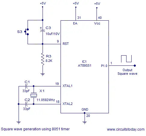
Square wave generation using 8051 timer.
Square waves of any frequency (limited
by the controller specifications) can be generated using the 8051 timer.
The technique is very simple. Write up a delay subroutine with delay
equal to half the time period of the square wave. Make any port pin high
and call the delay subroutine. After the delay subroutine is finished,
make the corresponding port pin low and call the delay subroutine gain.
After the subroutine is finished , repeat the cycle again. The result
will be a square wave of the desired frequency at the selected port pin.
The circuit diagram is shown below and it can be used for any square
wave, but the program has to be accordingly. Programs for different
square waves are shown below the circuit diagram.
Square wave generation using 8051 timer
1KHz Square wave using 8051 timer.
MOV P1,#00000000B
MOV TMOD,#00000001B
MAIN: SETB P1.0
      ACALL DELAY
      CLR P1.0
      ACALL DELAY
      SJMP MAIN
DELAY: MOV TH0,#0FEH
       MOV TL0,#00CH
       SETB TR0
HERE: JNB TF0,HERE
      CLR TR0
      CLR TF0
      SETB P1.0
      RET
      END
2 KHz Square wave using 8051 timer.
MOV P1,#00000000B
MOV TMOD,#00000001B
MAIN: SETB P1.0
      ACALL DELAY
      CLR P1.0
      ACALL DELAY
      SJMP MAIN
DELAY: MOV TH0,#0FCH
       MOV TL0,#018H
       SETB TR0
HERE:JNB TF0,HERE
     CLR TR0
     CLR TF0
     SETB P1.0
RET
END
10 KHz square wave using 8051 timer.
MOV P1,#00000000B
MOV TMOD,#00000001B
MAIN: SETB P1.0
      ACALL DELAY
      CLR P1.0
      ACALL DELAY
      SJMP MAIN
DELAY: MOV TH0,#0FFH
       MOV TL0,#0CEH
       SETB TR0
HERE:JNB TF0,HERE
     CLR TR0
     CLR TF0
     SETB P1.0
RET
END