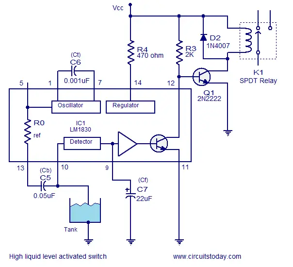
A method for activating a relay when the liquid level exceeds a predetermined level is shown here. DC voltage is required for driving the relay and AC voltage cannot be used here just like what we did in the case of LED and speaker. Pin 9 of the IC can be used to solve this problem. A capacitor connected from this pin to ground will keep the internal output transistor steadily ON whenever the probe resistance goes higher than the reference resistor. External transistor Q1 is connected to the collector of the internal transistor. The load that is the relay is connected at the collector of Q1. When the probe is not touching the water it equal to an open circuit situation and surely the probe resistance will be many M ohms and it is greater than the R
ref(13K). The internal transistor will be switched ON and Q1 whose base is connected to the collector of the internal transistor will be in OFF condition keeping the relay inactive. When the reverse scenario occurs (fluid level touches the probe) the internal transistor is switched OFF and this in turn makes the transistor Q1 ON resulting in the activation. The load connected through the relay whether pump, lamp, alarm, solenoid valve or anything is driven. Resistor R3 limits the collector current of the internal transistor while resistor R4 provides protection to the IC from transients.
High liquid level activated switch
Probe: The probe used here can be any metal rod with size and shape of your choice. The tank must be made of metal and it should be properly grounded. For non metal tanks fix a small metal contactor at its bottom level and ground it. The probe must be placed at the level you want to monitor.
Notes.
- The circuit can be assembled on a Perf board.
- I used 12V DC for powering the circuit.
- Maximum supply voltage LM1830 can handle is 28V.
- The tweeter I used was of a 16 ohm type.
- The relay I used is a 200 ohm/12V type.
- Maximum load current Q1 (2N2222) can handle is 800mA.
- The switching current/voltage ratings of the relay must be according to the load you want to drive using it.
- It is recommended to mount the IC on a holder.
Comments
Post a Comment